Latest products
kid crane riding toy
by:Dajin caster
2020-06-12
The first step is to lay out the parts of the crane on your wood to make sure you have all the parts you need.
The components have been laid out so that the 5\'x 3/4 \"plate of the Baltic birch plywood can be cut in half and still used for the project.
This can be easier if you don\'t have a truck to transport the full plywood.
Cut the plywood in half with a texture so that the preferred texture direction of the different workpiece can work.
See the following page for a more detailed layout of the crane boom.
I would suggest cutting out one of the boom and then cutting the matching boom with it.
We will discuss the issue in more detail later.
Put everything out of the sheet.
Aside from using the existing edges of plywood, leave 1/2 \"around all the components \".
Keep all waste wood for later use.
Label all rough cut pieces for easy identification.
Blue painter tape marked with black marks is perfect for this situation.
The blue painter tape is easier and cleaner than most other types of masking tape and keeps the material good.
In the picture behind the crane part, identify with the letters in the gray circle.
Remember, you can view pictures of different sizes by clicking \"I\" in the box in the upper left corner of each picture, including the original size.
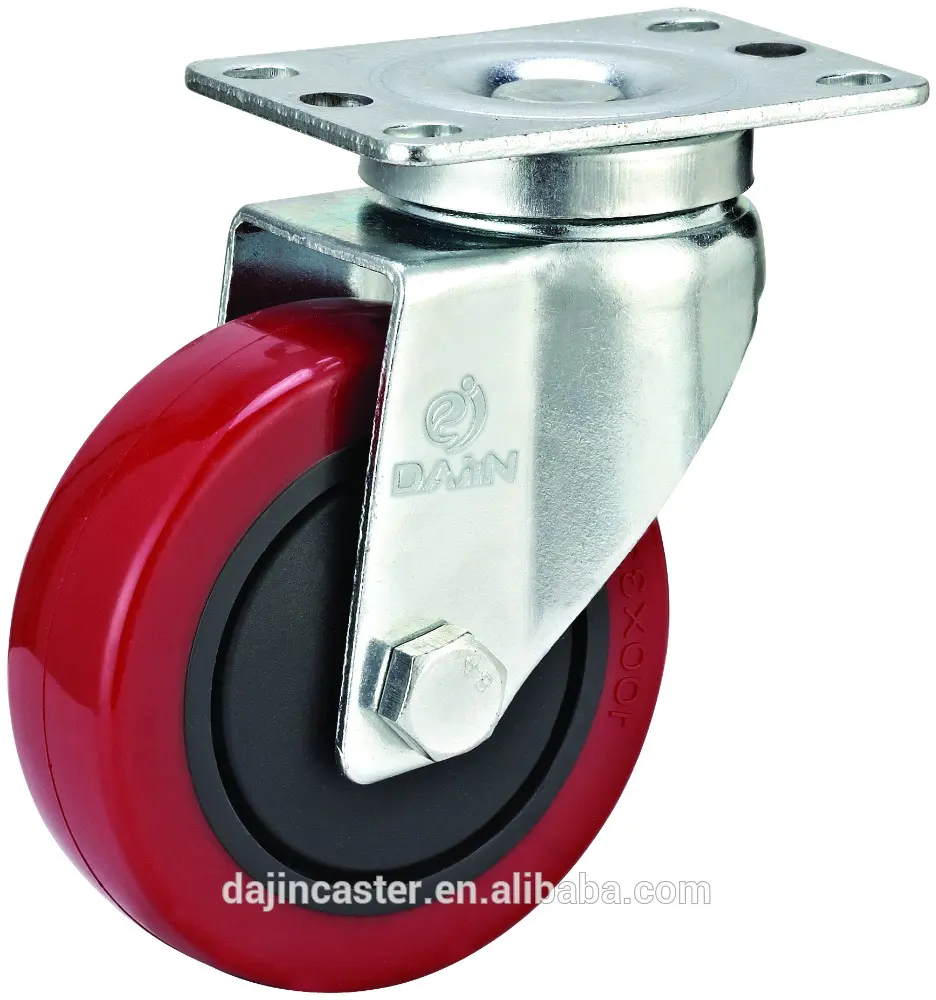
The crane rotates on three casters.
One of the casters must be modified to connect the sprocket to drive the wheel.
See Figure 1 below.
Take the casters apart as shown in Figure 2 below.
Drill two 11/64 diameter holes through the black caster hub.
You are right outside the Silver bearing assembly.
See Figure 3 below.
Use a tapping drill with 8x32 threads per inch at 18-
35 sprocket teeth.
Start the hole on the wheel hub side of the sprocket.
Tap holes using tap drill bit and \"T\" handle.
Slowly, often clean out the holes.
If you break the tapping hole drill bit in the hole, you may have to drill new holes that are offset from the old holes and tap on them.
See Figure 4 below.
Blow the threaded holes out using an air compressor or \"canned\" air.
In doing so, and the rest of the time working on the crane, make sure you wear safety glasses.
Connect the casters to the sprocket using 8x2 \"machine screws.
Pass the screw through the wheel and then through the hub side of the sprocket.
The head of the machine screw includes an 8-lock washer.
The screw should not extend the sprocket.
As shown in figure 5 below, reassemble the casters.
Replace the original 3/8 diameter bolt with the new 3 1/2 Bolt.
The completed assembly is shown in Figures 6, 7 and 8 below.
Connect the casters to the base with a diameter of x 1-1/4
1/4 \"long head machine screws.
Use a 1/4 lock washer and a 1/4 nyloc nut to prevent the casters from loosening.
See Figure 9 below.
Make sure that the bolts through the casters are aligned with the center of the base.
This will prevent the casters from sliding on the base when rotating.
Think of it as alignment of wheels on a car.
Use the dimensions in Figure 1 below to arrange the position of the casters on the base.
First drill a hole with a diameter of 1/4 on the workpiece.
It is recommended to use the router trammel to use a 1/4 hole when cutting the workpiece to the correct diameter.
It\'s just a material that can make your router a compass with a router at the end.
Draw a line from the center of the circle to the right of the circle, point 1.
We call it a horizontal reference line.
Using the protractor or the measurements below, arrange the line from the center of the circle to the points 2 and 3 where the casters are located.
See Figure 1 below. Measure 2-
3/8 \"up from the center of the circle to the bottom of 3\'long by 1\' wide slot with rounded ends.
This will be the slot for the chain to drive the casters through the circle.
Use a router bit with a radius of 1/8 to surround the outer top and bottom edges of the circle.
Mark the position of the casters and drill the mounting holes.
Make sure you drill perpendicular to the surface and use a piece of waste wood as a support so that the material is not torn when the drill bit goes through the plywood of 3/4.
See Pictures 2 and 3 below.
The crane needs two identical components.
Once you have cut out a boom side, you will use it to cut the matching sides along with the router template cut block.
Use the dimensions below to arrange the outline of the boom.
See Pictures 1, 2 and 3 below.
Before you cut the boom, make sure you draw everything through picture 3.
Drill holes as shown in the figure.
See Figures 2 and 3 below.
Backing blocks are used when drilling to prevent blow
When the hole is worn out, on the back of the workpiece.
When the project is completed, both sides of the plywood on many workpieces will be visible.
Use this finished part to track the Side block of another boom.
If possible, use a band saw to cut within 1/8 of the tracking profile.
Clamp the two parts together and trim the second side block to a side block that perfectly matches the other using a pattern wiring bit.
Flush cut router bit (
Guide bearing at the bottom)can be used.
See Figure 4 below.
Simply place the template pieces at the bottom and make sure the router height is adjusted correctly so that the rail bearing can ride along the edge of the piece to be copied.
Copper pipe fittings are used between the two sides of the boom to separate the two sides.
Measure the thickness of 3/4-3 pieces
Inch stock material used to determine the length of copper pipe required for the spacer device.
Cut 8 such long copper using the standard pipe cutter provided by any hardware store.
Make sure to remove the sharp edges on the cut pipe with a file or sandpaper.
Polish the copper tube with very fine sandpaper of 300 or higher.
Don\'t worry about polishing or polishing all the copper sheets very smooth.
Try to polish them into a uniform finish.
Longitudinal polishing is recommended.
Continue with the finer sand sandpaper and finish on your preferred copper tube.
Set the splinter end on a board with a protruding screw and spray the splinter with spray paint.
See Figure 5 below.
Apply a few layers of paint on the copper sheet for a lasting shine.
Copper pipes are fitted with nylon gaskets inside the pipe to limit movement in any direction.
Without the nylon gasket, the movement of the copper gasket will scratch the inner surface of the boom.
The transport bolt through the copper pipe is mounted with a nylon lock nut at the end.
See Figure 6 below.
Loosely assemble the sides of the boom with a copper gasket.
This step recommends two people, as the boom can easily turn over without a circular base.
Glue the three \"L\" blocks and place them between the two boom bars as shown in the following figure.
Mark the two holes as \"L\" blocks, where 1/4 of the carrying bolts will pass through the block from one side of the boom to the other.
Drill holes with a diameter of 1/4 through \"L.
See Pictures 1, 2 and 3 below.
In this step, we will modify one-
The child bicycle crank accepts 35 sprocket.
This will allow you to install the sprocket in the middle of the crank and hide the sprocket and chain in the center of the crane boom.
Remove the stub on the side of the crank first.
This can also be done as a later time.
See Figure 1 below.
Because the center of the single crank arm is 0.
The diameter is 75 \"and the thread is about 0.
865 \"then we have to create a gasket to fill the gap between the crank and the inner diameter of the sprocket 1 \".
Do this by bending the 1 \"1/8 wide\" thick aluminum bar in the center of the crank.
Clamp the crank onto the rod stock and bend the rod up and down at the center of the crank to create a \"U\" shape.
See Figure 2 below.
Make two identical pieces, as shown in Figures 3 and 4 below.
Cut off the half-circle end of the curved piece with a hacksaw.
You should end up with two pieces, as shown in figure 5 below.
Drill a hole with a diameter of 3/16 through the hub on 35 16-tooth sprocket.
Slide the sprocket over one-
Connect the crank to the center of the crank and check if the aluminum gasket you make is suitable between the sprocket and the crank.
See Figure 6 below.
Place the sprocket on the crank arm of the boom with the bearing.
Align the chain tooth with the opening in the base circle.
Mark the hole position on the aluminum gasket and crank and drill 3/16 through the gasket and crank.
The gasket should extend a maximum of 1/16 \"from the sprocket on the right side of the sprocket, as shown in figure 7 below. Insert a 2-
The inch length 8 32 TPI machine is screwed in through the sprocket, gasket and crank.
Fix the screw with nylon lock nut and cut off the excess thread.
The final length of 8 screws should be 1-3/4\".
See Figure 8 below.
Figure 9 shows a side view of the completed crank assembly.
Figure 10 shows the bottom bracket cup set and pedal.
The power of the pedal crank is sent to the drive caster by using the transfer lever.
The transfer rod is supported by two identical planks.
The transfer Rod is a 1/2 steel rod that transfers the rotation of the foot pedal to the caster drive wheel.
First make two identical parts for the end of the transfer bar.
See Figure 1 below.
As shown in Figure 2, set the bearing in the transfer rod end plate.
We start the layout of the part by placing a tape line from the axle driving the casters to the center of the base, as shown in figure 3.
This will be the layout line used to set the transfer rod end plate and the rest of the transfer Rod part.
As shown in figure 4, set the second tape parallel to the first, and one edge of the first tape intersect the center of the chain hole at the bottom.
The transfer Rod should be placed directly on the edge of this tape to keep all parts aligned.
As shown in figure 5, align the sprocket on the transfer rod with the sprocket on the drive caster.
This position sets the position of the end plate for this end of the transfer rod.
As shown in Figure 6, align the other sprocket with the opening in the base.
The two sprocket is connected to the 1/2 rod with 1-1
1/4 \"8 32 TPI machine screws and nylon lock nuts.
Once the sprocket position is set, you will need to go through the 1/2 \"bar.
If you can\'t find 1-
1/4 \"8 machine screws, then use 2\" long 8 machine screws to cut the sprocket into length after mounting it on the transfer rod.
Figure 8 shows the chain mounted on the drive casters.
As shown in Figure 9, install the chain from the sprocket on the foot crank to the transfer rod at the bottom of the crane.
Install the cover plate \"Y\" on the upper sprocket and chain \". Pre-
Drill holes on the assembly \"JKJ\" before installing the screws.
Attach the cover plate using 4 6 panhead wood screws, as shown in Figure 11, and see Figure 12 for the size and hole position of the cover plate.
The crane has two drum assemblies to be manufactured.
The drum consists of two parts-
Inner and Outer drums.
The inner drum is attached to the 1/2 \"steel shaft turned by a manual crank.
The inner drum uses a rare earth magnet with a diameter of 1/2 to drive the outer drum.
This effectively creates a sliding clutch for the drum and helps prevent heavy objects from hanging from the crane hook.
This will minimize the chance of the crane tilting if the child comes up and down from the crane with heavy load on the hook.
In Drum by diameter for 1/4 of 3/4 and 15/16 of Baltic Birch made.
These are glued together to form a 1 \"thick drum. Drill 1/2-
As shown in the upper right corner of the figure, the maget hole in inch diameter is 9/16 from the center of the workpiece \"Q\" and \"S.
If you do not want the magnet hub option in the crane, omit \"R\", \"S\", \"U\" and \"X\" and make two \"Q\" and \"T \".
For dimensions and material thickness, see Pictures 1 to 4 below.
See pictures of drums 5 and 6.
There are four magnets on both sides of the hub that can be used to increase the holding force and are recommended for use. See picture 7.
As shown in figure 8 below, glue the pieces together.
From the previous step, stick the part \"U\" to the assembly to complete the hub.
See Figure 9 below.
Drill a 3/8 diameter hole through the large hub at 5/16 speed from the inside of the part \"U.
Drill through the hub directly to the center.
Insert the internal magnetic hub and determine the position of the hole.
See Figure 10 below.
As shown in Figure 11 below, drill a hole with a diameter of 3/8 into the workpiece \"S. Pre-
Drill a hole with a diameter of 1/8.
The finished hub shown in Figure 12.
The drum or hub is assembled from 1/4 thick, 1/2 thick Baltic birch plywood.
Cut two circles with a diameter of 1-1/4
The diameter is 3/4 \"and the center hole is 1/4 \".
Cut 1 circle with a diameter of 1-1/2
The diameter is 1/4 \"and the center hole is 1/4 \". See picture 13.
Glue the three circles together with the larger diameter circles on the outside to form the hub, as shown in Figure 12.
When the circle is bonded together, use a bracket bolt or a pin with a diameter of 1/4 to keep the circle aligned.
Using the dimensions in Figure 1 below, cut the brake gear from a 3/4 thick Baltic birch tree.
Use a brad point or forsner drill bit with a diameter of 3/4 to drill into the inner radius first, and then use a band saw to remove the scrap of the outer radius.
Finally, smooth the edges to the template below using the spindle sander.
Bypass all edges on both sides with a 1/8 router bit.
See Figure 2 for the installed brake gear.
For the dimensions of the brake handle, see the following figure.
Keep in mind that you can view the full size image by clicking \"I\" in the upper left corner of the picture and selecting the desired scale.
This one is made by 3/4
Inch thick material.
This is the hand crank of the crane on the crane.
For more details on this article, see Pictures 1 and 2 below.
See Figure 3 for finished products.
Cut one of the nylon gaskets so that the transport bolts are screwed into the 1/4 \"insert\" N and flush with the back of the piece.
See Figure 4 below.
Cut the copper sheet to grow 1/32 \"less than the space between the washers \".
This will allow it to rotate freely on the nylon gasket.
See Figure 5 below.
Another view of the handle component is shown in figure 6.
Mount the magnetic hub on a steel rod with a diameter of 1/2, with a 1/2 flat gasket on both sides to keep it centered between the boom side blocks.
Add a 1/2 \"flat floor washer to the steel bar on the outside between the boom side and the brake gear.
To make the magnetic hub work like a solid hub, then extend the fixing screw back until it extends to the external magnetic hub, but still through the 1/2 steel rod.
See Figure 1 below.
Use 1-1 to install the brake gear as shown in the following figure
5/8 \"gold rough screws.
1/2 \"steel bars need to be cut off with a crank handle\" N \"outside the brake gear\" O \"and on the other side of the crane.
It is recommended to do so after installing the brake gear and the crank handle.
See Figure 2 below.
Install the brake handle \"P\" at the end of the 5 \"carriage bolt, as shown in figure 3 below.
Between the brake handle and the boom include nylon or plastic flat washers with a diameter of 1/4. See picture 5.
Add another 1/4 nylon flat washer to the outside of the brake handle.
Done by installing the 1/4 \"nylon lock nut and 1/4\" cap, as shown in Figure 6 below.
Let the brake handle \"P\" stay on the brake gear \"O\" as shown in Figure 4 below.
The hole at 1/4 \"insert\" E \"in the arm at the top of the brake handle slot is marked as\" down \"position.
Remove the brake handle and drill a 3/8 diameter hole for the 1/4 insert.
The hole should be only 1/2 deep.
Be careful not to drill holes all the time on the side of the boom.
Reduce the brake handle and install 1/4 \"-20 x 1-
1/2 \"cap screws as shown on the top right.
Install the hand crank using 2 \"gold thick wood screws.
Make sure to insert a 1/2 flat gasket between the manual crank and the boom on the 1/2 steel rod. See picture 7.
Cut all 5 seats into size as shown below.
The top of the seat is secured in place by 4 pocket screws.
If you are unable to use the pocket screw fixture, use an alternative connection method.
For the dimensions and hole position of the seat parts, see Pictures 1 to 5.
1-for pocket holes1/4\" (32mm)
Washer head for Baltic birch 2 square drive thick screws.
Recommend material according to the type of material you use for your seat.
Drill pocket holes for the top and hole of the seat, connect the seat back to the side of the seat, and the side of the seat to the front of the seat. See picture 6.
Fully assemble the seat as shown in Figure 7.
Wait until the boom is fully installed before connecting the horizontal seat Part G.
After unloading the crane, it will be easier to build the rest of the crane.
Use painter tape to mark the sides of the seat using the center reference mark of the crane seat.
Next, place the assembled seat between the tape marks and position it so that the seat back is not hung on the curved edge of the base ring.
Place a line of tape before and after the seat to mark the full profile of the seat.
Mark and drill holes to connect the seat to the base circle as shown in figure 8 below.
To be located on the side of the seat and in the center of the seat back, these holes need to be drilled 3/8 from the painter tape.
As shown in Figure 9, secure the seat on the base circle using tape alignment.
2 \"drill holes and countersunk holes for long 8 Gold thick deck screws, attach the seat to the base.
Find a hook you want to use for the crane.
If you use a bungee line hook, make sure that it is designed with a bungee line diameter of about 1/4.
See Figure 1 below.
We modified the hook as shown in figure 2 so that the kids can hook things more easily.
The crane uses a rope of 1/4.
For the building theme, we used the black and yellow ropes shown in figure 3. .
Slide the ball at the end of the rope, then slide the hook.
Make a knot at the end of the rope to prevent it from passing through the hook.
Knots on certain types of ropes sometimes pull out or wear out.
You can gently melt the end of the rope or cover it with epoxy to help prevent this from happening. See picture 4.
Use the 3/8 Brad point drill at 1-
The ball is 1/2 in diameter.
Gently clip the ball between the two plates on the drill press. Pre-
Drill holes on the top plate and feed the drill bit slowly.
See Figure 4 for super balls on the rope.
As shown in Figure 6, cover the last 3/4 of the rope with a thick layer of epoxy resin.
Epoxy helps secure the rope in the holes on the drum and prevents end wear.
A little light sanding can handle the thick points on the epoxy resin, which is too thick for the holes on the drum. That\'s it!
After the epoxy is cured, you can put the rope on the crane to make the kids have fun.
Since this is made with heavy parts, even adults can have a good time with this toy.
The components have been laid out so that the 5\'x 3/4 \"plate of the Baltic birch plywood can be cut in half and still used for the project.
This can be easier if you don\'t have a truck to transport the full plywood.
Cut the plywood in half with a texture so that the preferred texture direction of the different workpiece can work.
See the following page for a more detailed layout of the crane boom.
I would suggest cutting out one of the boom and then cutting the matching boom with it.
We will discuss the issue in more detail later.
Put everything out of the sheet.
Aside from using the existing edges of plywood, leave 1/2 \"around all the components \".
Keep all waste wood for later use.
Label all rough cut pieces for easy identification.
Blue painter tape marked with black marks is perfect for this situation.
The blue painter tape is easier and cleaner than most other types of masking tape and keeps the material good.
In the picture behind the crane part, identify with the letters in the gray circle.
Remember, you can view pictures of different sizes by clicking \"I\" in the box in the upper left corner of each picture, including the original size.
The crane rotates on three casters.
One of the casters must be modified to connect the sprocket to drive the wheel.
See Figure 1 below.
Take the casters apart as shown in Figure 2 below.
Drill two 11/64 diameter holes through the black caster hub.
You are right outside the Silver bearing assembly.
See Figure 3 below.
Use a tapping drill with 8x32 threads per inch at 18-
35 sprocket teeth.
Start the hole on the wheel hub side of the sprocket.
Tap holes using tap drill bit and \"T\" handle.
Slowly, often clean out the holes.
If you break the tapping hole drill bit in the hole, you may have to drill new holes that are offset from the old holes and tap on them.
See Figure 4 below.
Blow the threaded holes out using an air compressor or \"canned\" air.
In doing so, and the rest of the time working on the crane, make sure you wear safety glasses.
Connect the casters to the sprocket using 8x2 \"machine screws.
Pass the screw through the wheel and then through the hub side of the sprocket.
The head of the machine screw includes an 8-lock washer.
The screw should not extend the sprocket.
As shown in figure 5 below, reassemble the casters.
Replace the original 3/8 diameter bolt with the new 3 1/2 Bolt.
The completed assembly is shown in Figures 6, 7 and 8 below.
Connect the casters to the base with a diameter of x 1-1/4
1/4 \"long head machine screws.
Use a 1/4 lock washer and a 1/4 nyloc nut to prevent the casters from loosening.
See Figure 9 below.
Make sure that the bolts through the casters are aligned with the center of the base.
This will prevent the casters from sliding on the base when rotating.
Think of it as alignment of wheels on a car.
Use the dimensions in Figure 1 below to arrange the position of the casters on the base.
First drill a hole with a diameter of 1/4 on the workpiece.
It is recommended to use the router trammel to use a 1/4 hole when cutting the workpiece to the correct diameter.
It\'s just a material that can make your router a compass with a router at the end.
Draw a line from the center of the circle to the right of the circle, point 1.
We call it a horizontal reference line.
Using the protractor or the measurements below, arrange the line from the center of the circle to the points 2 and 3 where the casters are located.
See Figure 1 below. Measure 2-
3/8 \"up from the center of the circle to the bottom of 3\'long by 1\' wide slot with rounded ends.
This will be the slot for the chain to drive the casters through the circle.
Use a router bit with a radius of 1/8 to surround the outer top and bottom edges of the circle.
Mark the position of the casters and drill the mounting holes.
Make sure you drill perpendicular to the surface and use a piece of waste wood as a support so that the material is not torn when the drill bit goes through the plywood of 3/4.
See Pictures 2 and 3 below.
The crane needs two identical components.
Once you have cut out a boom side, you will use it to cut the matching sides along with the router template cut block.
Use the dimensions below to arrange the outline of the boom.
See Pictures 1, 2 and 3 below.
Before you cut the boom, make sure you draw everything through picture 3.
Drill holes as shown in the figure.
See Figures 2 and 3 below.
Backing blocks are used when drilling to prevent blow
When the hole is worn out, on the back of the workpiece.
When the project is completed, both sides of the plywood on many workpieces will be visible.
Use this finished part to track the Side block of another boom.
If possible, use a band saw to cut within 1/8 of the tracking profile.
Clamp the two parts together and trim the second side block to a side block that perfectly matches the other using a pattern wiring bit.
Flush cut router bit (
Guide bearing at the bottom)can be used.
See Figure 4 below.
Simply place the template pieces at the bottom and make sure the router height is adjusted correctly so that the rail bearing can ride along the edge of the piece to be copied.
Copper pipe fittings are used between the two sides of the boom to separate the two sides.
Measure the thickness of 3/4-3 pieces
Inch stock material used to determine the length of copper pipe required for the spacer device.
Cut 8 such long copper using the standard pipe cutter provided by any hardware store.
Make sure to remove the sharp edges on the cut pipe with a file or sandpaper.
Polish the copper tube with very fine sandpaper of 300 or higher.
Don\'t worry about polishing or polishing all the copper sheets very smooth.
Try to polish them into a uniform finish.
Longitudinal polishing is recommended.
Continue with the finer sand sandpaper and finish on your preferred copper tube.
Set the splinter end on a board with a protruding screw and spray the splinter with spray paint.
See Figure 5 below.
Apply a few layers of paint on the copper sheet for a lasting shine.
Copper pipes are fitted with nylon gaskets inside the pipe to limit movement in any direction.
Without the nylon gasket, the movement of the copper gasket will scratch the inner surface of the boom.
The transport bolt through the copper pipe is mounted with a nylon lock nut at the end.
See Figure 6 below.
Loosely assemble the sides of the boom with a copper gasket.
This step recommends two people, as the boom can easily turn over without a circular base.
Glue the three \"L\" blocks and place them between the two boom bars as shown in the following figure.
Mark the two holes as \"L\" blocks, where 1/4 of the carrying bolts will pass through the block from one side of the boom to the other.
Drill holes with a diameter of 1/4 through \"L.
See Pictures 1, 2 and 3 below.
In this step, we will modify one-
The child bicycle crank accepts 35 sprocket.
This will allow you to install the sprocket in the middle of the crank and hide the sprocket and chain in the center of the crane boom.
Remove the stub on the side of the crank first.
This can also be done as a later time.
See Figure 1 below.
Because the center of the single crank arm is 0.
The diameter is 75 \"and the thread is about 0.
865 \"then we have to create a gasket to fill the gap between the crank and the inner diameter of the sprocket 1 \".
Do this by bending the 1 \"1/8 wide\" thick aluminum bar in the center of the crank.
Clamp the crank onto the rod stock and bend the rod up and down at the center of the crank to create a \"U\" shape.
See Figure 2 below.
Make two identical pieces, as shown in Figures 3 and 4 below.
Cut off the half-circle end of the curved piece with a hacksaw.
You should end up with two pieces, as shown in figure 5 below.
Drill a hole with a diameter of 3/16 through the hub on 35 16-tooth sprocket.
Slide the sprocket over one-
Connect the crank to the center of the crank and check if the aluminum gasket you make is suitable between the sprocket and the crank.
See Figure 6 below.
Place the sprocket on the crank arm of the boom with the bearing.
Align the chain tooth with the opening in the base circle.
Mark the hole position on the aluminum gasket and crank and drill 3/16 through the gasket and crank.
The gasket should extend a maximum of 1/16 \"from the sprocket on the right side of the sprocket, as shown in figure 7 below. Insert a 2-
The inch length 8 32 TPI machine is screwed in through the sprocket, gasket and crank.
Fix the screw with nylon lock nut and cut off the excess thread.
The final length of 8 screws should be 1-3/4\".
See Figure 8 below.
Figure 9 shows a side view of the completed crank assembly.
Figure 10 shows the bottom bracket cup set and pedal.
The power of the pedal crank is sent to the drive caster by using the transfer lever.
The transfer rod is supported by two identical planks.
The transfer Rod is a 1/2 steel rod that transfers the rotation of the foot pedal to the caster drive wheel.
First make two identical parts for the end of the transfer bar.
See Figure 1 below.
As shown in Figure 2, set the bearing in the transfer rod end plate.
We start the layout of the part by placing a tape line from the axle driving the casters to the center of the base, as shown in figure 3.
This will be the layout line used to set the transfer rod end plate and the rest of the transfer Rod part.
As shown in figure 4, set the second tape parallel to the first, and one edge of the first tape intersect the center of the chain hole at the bottom.
The transfer Rod should be placed directly on the edge of this tape to keep all parts aligned.
As shown in figure 5, align the sprocket on the transfer rod with the sprocket on the drive caster.
This position sets the position of the end plate for this end of the transfer rod.
As shown in Figure 6, align the other sprocket with the opening in the base.
The two sprocket is connected to the 1/2 rod with 1-1
1/4 \"8 32 TPI machine screws and nylon lock nuts.
Once the sprocket position is set, you will need to go through the 1/2 \"bar.
If you can\'t find 1-
1/4 \"8 machine screws, then use 2\" long 8 machine screws to cut the sprocket into length after mounting it on the transfer rod.
Figure 8 shows the chain mounted on the drive casters.
As shown in Figure 9, install the chain from the sprocket on the foot crank to the transfer rod at the bottom of the crane.
Install the cover plate \"Y\" on the upper sprocket and chain \". Pre-
Drill holes on the assembly \"JKJ\" before installing the screws.
Attach the cover plate using 4 6 panhead wood screws, as shown in Figure 11, and see Figure 12 for the size and hole position of the cover plate.
The crane has two drum assemblies to be manufactured.
The drum consists of two parts-
Inner and Outer drums.
The inner drum is attached to the 1/2 \"steel shaft turned by a manual crank.
The inner drum uses a rare earth magnet with a diameter of 1/2 to drive the outer drum.
This effectively creates a sliding clutch for the drum and helps prevent heavy objects from hanging from the crane hook.
This will minimize the chance of the crane tilting if the child comes up and down from the crane with heavy load on the hook.
In Drum by diameter for 1/4 of 3/4 and 15/16 of Baltic Birch made.
These are glued together to form a 1 \"thick drum. Drill 1/2-
As shown in the upper right corner of the figure, the maget hole in inch diameter is 9/16 from the center of the workpiece \"Q\" and \"S.
If you do not want the magnet hub option in the crane, omit \"R\", \"S\", \"U\" and \"X\" and make two \"Q\" and \"T \".
For dimensions and material thickness, see Pictures 1 to 4 below.
See pictures of drums 5 and 6.
There are four magnets on both sides of the hub that can be used to increase the holding force and are recommended for use. See picture 7.
As shown in figure 8 below, glue the pieces together.
From the previous step, stick the part \"U\" to the assembly to complete the hub.
See Figure 9 below.
Drill a 3/8 diameter hole through the large hub at 5/16 speed from the inside of the part \"U.
Drill through the hub directly to the center.
Insert the internal magnetic hub and determine the position of the hole.
See Figure 10 below.
As shown in Figure 11 below, drill a hole with a diameter of 3/8 into the workpiece \"S. Pre-
Drill a hole with a diameter of 1/8.
The finished hub shown in Figure 12.
The drum or hub is assembled from 1/4 thick, 1/2 thick Baltic birch plywood.
Cut two circles with a diameter of 1-1/4
The diameter is 3/4 \"and the center hole is 1/4 \".
Cut 1 circle with a diameter of 1-1/2
The diameter is 1/4 \"and the center hole is 1/4 \". See picture 13.
Glue the three circles together with the larger diameter circles on the outside to form the hub, as shown in Figure 12.
When the circle is bonded together, use a bracket bolt or a pin with a diameter of 1/4 to keep the circle aligned.
Using the dimensions in Figure 1 below, cut the brake gear from a 3/4 thick Baltic birch tree.
Use a brad point or forsner drill bit with a diameter of 3/4 to drill into the inner radius first, and then use a band saw to remove the scrap of the outer radius.
Finally, smooth the edges to the template below using the spindle sander.
Bypass all edges on both sides with a 1/8 router bit.
See Figure 2 for the installed brake gear.
For the dimensions of the brake handle, see the following figure.
Keep in mind that you can view the full size image by clicking \"I\" in the upper left corner of the picture and selecting the desired scale.
This one is made by 3/4
Inch thick material.
This is the hand crank of the crane on the crane.
For more details on this article, see Pictures 1 and 2 below.
See Figure 3 for finished products.
Cut one of the nylon gaskets so that the transport bolts are screwed into the 1/4 \"insert\" N and flush with the back of the piece.
See Figure 4 below.
Cut the copper sheet to grow 1/32 \"less than the space between the washers \".
This will allow it to rotate freely on the nylon gasket.
See Figure 5 below.
Another view of the handle component is shown in figure 6.
Mount the magnetic hub on a steel rod with a diameter of 1/2, with a 1/2 flat gasket on both sides to keep it centered between the boom side blocks.
Add a 1/2 \"flat floor washer to the steel bar on the outside between the boom side and the brake gear.
To make the magnetic hub work like a solid hub, then extend the fixing screw back until it extends to the external magnetic hub, but still through the 1/2 steel rod.
See Figure 1 below.
Use 1-1 to install the brake gear as shown in the following figure
5/8 \"gold rough screws.
1/2 \"steel bars need to be cut off with a crank handle\" N \"outside the brake gear\" O \"and on the other side of the crane.
It is recommended to do so after installing the brake gear and the crank handle.
See Figure 2 below.
Install the brake handle \"P\" at the end of the 5 \"carriage bolt, as shown in figure 3 below.
Between the brake handle and the boom include nylon or plastic flat washers with a diameter of 1/4. See picture 5.
Add another 1/4 nylon flat washer to the outside of the brake handle.
Done by installing the 1/4 \"nylon lock nut and 1/4\" cap, as shown in Figure 6 below.
Let the brake handle \"P\" stay on the brake gear \"O\" as shown in Figure 4 below.
The hole at 1/4 \"insert\" E \"in the arm at the top of the brake handle slot is marked as\" down \"position.
Remove the brake handle and drill a 3/8 diameter hole for the 1/4 insert.
The hole should be only 1/2 deep.
Be careful not to drill holes all the time on the side of the boom.
Reduce the brake handle and install 1/4 \"-20 x 1-
1/2 \"cap screws as shown on the top right.
Install the hand crank using 2 \"gold thick wood screws.
Make sure to insert a 1/2 flat gasket between the manual crank and the boom on the 1/2 steel rod. See picture 7.
Cut all 5 seats into size as shown below.
The top of the seat is secured in place by 4 pocket screws.
If you are unable to use the pocket screw fixture, use an alternative connection method.
For the dimensions and hole position of the seat parts, see Pictures 1 to 5.
1-for pocket holes1/4\" (32mm)
Washer head for Baltic birch 2 square drive thick screws.
Recommend material according to the type of material you use for your seat.
Drill pocket holes for the top and hole of the seat, connect the seat back to the side of the seat, and the side of the seat to the front of the seat. See picture 6.
Fully assemble the seat as shown in Figure 7.
Wait until the boom is fully installed before connecting the horizontal seat Part G.
After unloading the crane, it will be easier to build the rest of the crane.
Use painter tape to mark the sides of the seat using the center reference mark of the crane seat.
Next, place the assembled seat between the tape marks and position it so that the seat back is not hung on the curved edge of the base ring.
Place a line of tape before and after the seat to mark the full profile of the seat.
Mark and drill holes to connect the seat to the base circle as shown in figure 8 below.
To be located on the side of the seat and in the center of the seat back, these holes need to be drilled 3/8 from the painter tape.
As shown in Figure 9, secure the seat on the base circle using tape alignment.
2 \"drill holes and countersunk holes for long 8 Gold thick deck screws, attach the seat to the base.
Find a hook you want to use for the crane.
If you use a bungee line hook, make sure that it is designed with a bungee line diameter of about 1/4.
See Figure 1 below.
We modified the hook as shown in figure 2 so that the kids can hook things more easily.
The crane uses a rope of 1/4.
For the building theme, we used the black and yellow ropes shown in figure 3. .
Slide the ball at the end of the rope, then slide the hook.
Make a knot at the end of the rope to prevent it from passing through the hook.
Knots on certain types of ropes sometimes pull out or wear out.
You can gently melt the end of the rope or cover it with epoxy to help prevent this from happening. See picture 4.
Use the 3/8 Brad point drill at 1-
The ball is 1/2 in diameter.
Gently clip the ball between the two plates on the drill press. Pre-
Drill holes on the top plate and feed the drill bit slowly.
See Figure 4 for super balls on the rope.
As shown in Figure 6, cover the last 3/4 of the rope with a thick layer of epoxy resin.
Epoxy helps secure the rope in the holes on the drum and prevents end wear.
A little light sanding can handle the thick points on the epoxy resin, which is too thick for the holes on the drum. That\'s it!
After the epoxy is cured, you can put the rope on the crane to make the kids have fun.
Since this is made with heavy parts, even adults can have a good time with this toy.
Custom message