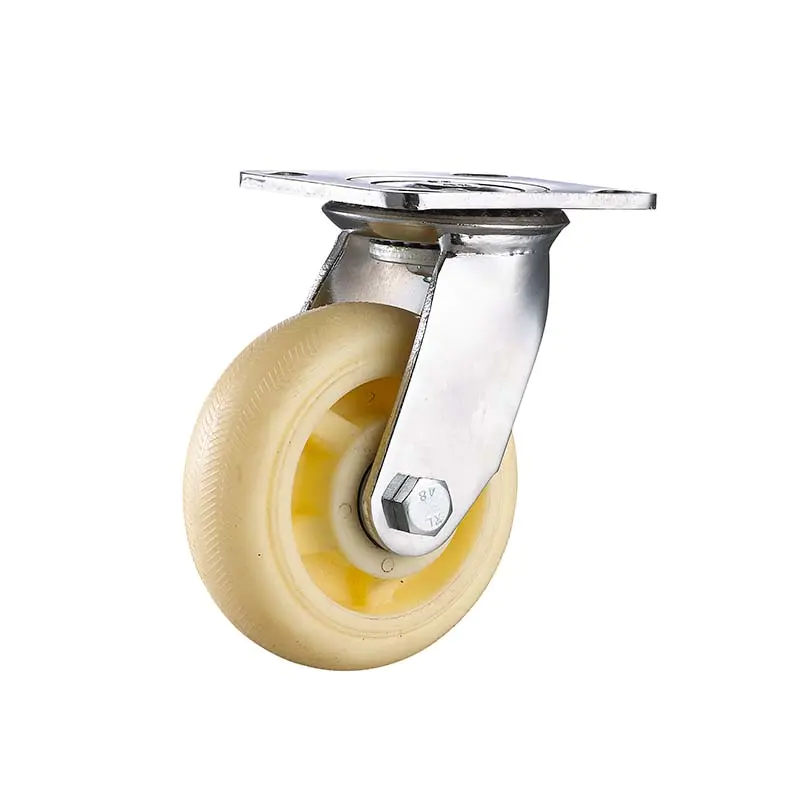
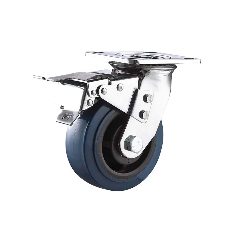
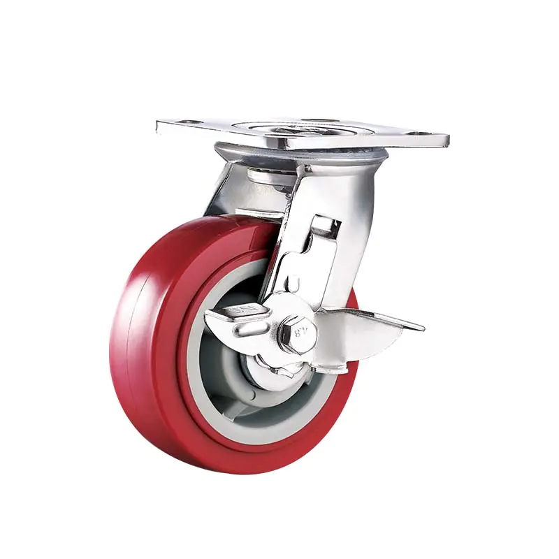
Medium heavy duty PU caster wheel for Roll container warehouse Logistic cargo cart
Medium-heavy duty caster
play station remote controlled wireless 3d printed car
by:Dajin caster
2020-06-12
Who doesn\'t like games?
Racing and fighting in the virtual world of game stations and Xbox! !
So, in order to have fun with real life, I made this Instructure, in this Instructure I will show you how to use any Play Station remote (Wired/Wireless)
Wirelessly control your electronics/robotics projects with easy-to-use components.
So take your old game Station Remote and start building! !
I converted an old car made of a kit purchased from a local store into a wireless station remote control car.
Here, I have created and attached the design of the required parts in the kit that makes the car chassis.
Feel free to use, or make your own car by modifying the design! ! 1)
The core of this building is the game station controller itself. (Wired/Wireless)2)
The brain of the tissue is Arduino UNO/NANO.
Two Planks are needed-
One for the receiver side and the other for the sender side. 3)2 X HC-
12 wireless serial communication module or any other wireless communication module (
No need if you have a wireless station controller). 4)
Dual-Channel motor drive module. 5)
2 x dc deceleration Motor 6)
1 X casters 7)2 X Wheels8)
6 X shaft lock and Bolt9)12 X 0.
4 \"bolts and nuts8 X Spacers (
2 long and 6 short)10)2 X Bolts 1. 5\" and Nuts11)
Some jumpers Wires12)
12v LiPo battery for power supply 1)
Install the casters on the bottom with two small L pieces, with a bolt and nut at each end. 2)
Attach the caster mounting plate to the rectangular plate with the help of tiny L-pieces, bolts and nuts. 3)
Fix the two C-shaped plates with two nuts and bolts on the two relative widths of the rectangular plates. 1)
Place the motor inside the C-plate so that the motor cable comes out of the third hole in the front of the chassis and tighten them. 2)
Place the motor drive module roughly between the two motors on the rectangular plate and tighten it with some small bolts and nuts.
Since my chassis is made of aluminum, to prevent any shorts, I placed two rubber washers between the motor drive module and the rectangular plate. 3)
Weld two wires on two terminals of two motors and attach them to the specified position on the motor drive. 4)
Use 1 to place other rectangular plates on the top of the motor drive.
5 \'\'bolts and 3 nuts each so that the plate does not touch the motor drive below. 1)
Use the small gasket in the middle to connect the smaller gear to the motor cable and fix it in place using the shaft lock at the other end. 2)
Place the wheel and the larger gear on the shaft and place it next to the smaller gear, with a small gasket between the gear and the plate. 3)
Use the shaft lock at both ends to lock the shaft in place.
The structure of the car has been completed, now is the time for electronic products! !
The connection is as follows: transmitter side: Arduino and HC-
12: 5 V of Arduino--->VCC of HC-
12GND of Arduino--->GND of HC-
12pin 6 of Arduino--->TX pin of HC-
12pin 7 of Arduino--->RX pin of HC-
12Arduino and PS controllers: 3. 3V of arduino---
> VCC for Arduino controller---
> GND for Arduino controller pin 5---
> Clock pin for Arduino controller pin 4---
> Command pin for Arduino controller pin 3---
> Attention pin for Arduino controller pin 2---
> Controller receiver side data pins: Arduino and HC-
12: 5 V of Arduino--->VCC of HC-
12GND of Arduino--->GND of HC-
12-pin Arduino 2-->TX pin of HC-
12-pin Arduino 3-->RX pin of HC-
Arduino and motor driver: GND-of arduino---
> GND of motor drive pin 4 for Arduino---
> In1 of motor drive pin 5 for Arduino---
> In2 of motor drive pin 6 for Arduino---
> In3 of motor drive pin 7 of Arduino---
> The in4 of the motor driver supplies power to the motor driver and Arduino with a 12 v LiPo battery.
Install the PS2X arduino library for a given code.
Custom message
Related Products